Introduction
One of my hobbies is audio. I have been avidly updating my turntable setup which is a vintage Thorens TD-124 unit I inherited from my father. Over the years I have serviced its motor, had the bearing professionally refurbished and have updated various parts in the effort of making it a table comparable to a modern turntable, but with a retro flair. The Thorens was considered a marvel of its day with low wow and flutter measurements, reasonably low rumble and the ability to run all day (it was a transcription table used in radio stations like its competitor the EMT-930). The Thorens is an idler design which means it has a complex mechanical and belt mechanism that takes a shaded pole induction motor (controlled by the wall voltage and phase) and uses a belt to turn a pulley. This pulley has precisely calibrated steps that in turn an idler wheel that drives the rim of the platter itself. The Thorens supports 16, 33.3, 45 and 78 rpm speeds. Because there are a lot of moving parts, it can be hard to get one to perform at peak levels.
Online there are some very active forums dedicated to this and other idler turntables – they do sound terrific and there is an active community maintaining and enhancing them. A few key companies like Hanze Hi-Fi and Woodsong Audio have push the state of the art through engineering and measurement. Jaap Pees at Hanze has an extensive setup where he measures the improvements he makes. This has led to a number of discoveries like the motor suspension springs to isolate the E50 motor from the turntable body. I wanted to check if my mods had a positive or negative effect on the vibrations of the tonearm – this is where the signal of the cartridge is picked up, so if you can detect vibration there, it can make it into the signal path.
Jaap uses professional level equipment from Brüel & Kjær which is lab quality and very expensive. I wanted to see if my Arduino hacking could get similar results as his equipment at a fraction of the cost. When I started looking, there were a number of different types of sensors: mems, mechanical, and piezo-ceramic. I wanted to explore which one(s) were the most sensitive for detecting vibrations of my turntable. So I ordered a sample of each type.
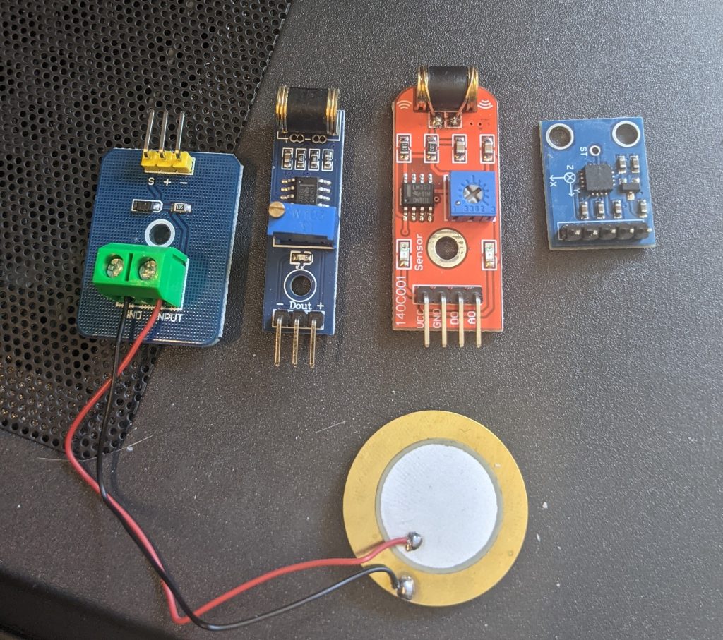
Mems ADXL335 Sensor
I started with this type of sensor because I had read it was pretty sensitive. I have seen MEMS sensors in other applications and thought it would be a good fit for this problem. I researched which MEMS is the most sensitive and the ADXL335 seemed to be the recommendation from Analog Devices. This is typically used for things like device orientation as well as acceleration. It has outputs in 3-axes X, Y, Z. I read some white papers that inspired me to start here and I built the testing code based on this Measuring mechanical vibrations
using an Arduino as a slave I/O to an EPICS control system by Adam Hjort & Mäns Holmberg from the University of Uppsala Sweden. The were using this exact device along with a controller called EPIC to use an Arduino and this board to record vibrations taken during experiments and subtract them out. I felt that the code they wrote and FFT analysis was worth using and then comparing with sensors for sensitivity.
Piezo-Ceramic Disk Sensor
I was inspired by this blog – the author built his own system to hook up to the raw piezo sensor. There are a number of inexpensive options that come as boards with amplifiers on Amazon and other sources. This is a very inexpensive solution and the original design by Doug Houlding was full of good insights. The first was that the actual sensor disc needs to be mass loaded to get some good results from this type of sensor. That makes sense because without some mass, the disc will just bounce on top of the measurement surface. Doug’s original application was a burglar alarm type of sensor, so his code was more interested in a threshold based measurement. His circuit is very similar to the amplifier with Zener diode to prevent over-voltage. Piezo-ceramics are capable of some very high voltages and without protection, they could easily damage the analog inputs of an Arduino board.
Mechanical 820s Sensors
These two sensors are very similar. One has a “digital” only output and the other has both an analog and digital output. These work by having some very small ball bearings inside the drum that jostle around and register voltages that are then amplified for the output. It’s not full clear how the analog version of the output differs, but I felt it would be good to have both types to compare how they worked in the real world.